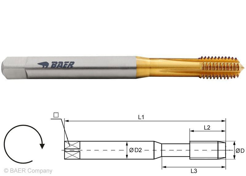
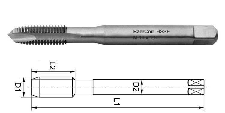
BaerCoil HSSE-TiN Forming Tap M 4 x 0.7 STI (oversized for wire thread inserts)
In stock
Express shipping available
BaerCoil HSSE-TiN Forming Tap M 4 x 0.7 STI (oversized for wire thread inserts)
BaerCoil® Machine forming taps are mainly used to repair threads or to reinforce threads in conjunction with wire thread inserts. The forming tap is used to produce the holding thread for thread inserts of dimension M 4 x 0.7. The receiving thread for wire thread inserts M 4 x 0.7 is also called STI thread (screw thread insert) or STI thread (Screw Thread Insert) and has an oversize so that after installation of the thread insert the normal output thread M 4 x 0.7 is produced again
Forming taps are also referred to as fluteless tap and have the task of deforming or plasticising the material. This material compression causes a compression of the holding thread. The result: The thread into which the BaerCoil® wire thread insert is screwed has a significantly higher load capacity. In addition, thread forming is clearly superior to thread cutting. It is faster, the surface finish is better, there are no chips. The forming tap has a longer service life.
During thread forming, the fibres of the material are compressed by the polygonal profile and not - as with thread cutting - cut through. This results in a higher material strength and a smooth surface. Small forming pockets are formed at the tips of the resulting thread.
Since high frictional forces occur during thread forming, care must be taken to ensure sufficient lubrication. oil grooves provide the necessary lubrication up to a depth of 2.5 D.
Not all materials are suitable for cold forming. Light metals, pure titanium, non-ferrous metals and steels, among others, are well suited. The required torques cannot be achieved with manual application. Mechanical application is therefore unavoidable.
The combination of BaerCoil® thread forming and BaerCoil® wire thread inserts opens up new dimensions in the design, development of new and improvement of existing components. Tensile tests for this purpose were carried out in the mechanical testing laboratory CryoMaK at the Institute of Technical Physics of the Karlsruhe Institute of Technology (KIT).
Advantages of forming taps
- No chips are produced
- Up to 20 times higher tool life time (compared to taps)
- Simultaneously for through hole and blind hole
- Wide range of materials can be machined
- Wrong cutting of the thread is impossible
- No pitch or flank angle errors
- Very true to gauge
- Higher strength of the holding thread due to material deformation or uninterrupted fibre flow
- Higher surface quality
- Much higher cutting speed
Comparison

Baercoil®
and cut thread
and formed thread


Dimensions
| Diameter |
4 |
|---|---|
| Nominal diameter in inches |
0,194 |
| Nominal diameter in mm |
4,94 |
| Pitch |
0,7 |
| Pitch in mm |
0,7 |
| Dimension |
M 4 x 0,7 EG/STI |
| Square |
4,9 mm |
Characteristics
| Product group |
Forming Taps Wire thread inserts - Taps |
|---|---|
| Product type |
BaerCoil thread forming taps |
| Thread standard |
M EG/STI: Metric ISO standard thread for wire thread inserts according to DIN 8140-2 |
| Tolerance |
ISO2/6HX mod. |
| Direction |
Right |
| Standard |
Factory standard |
| Tensile strength at room temperature |
up to 850 N/mm² | 25.5 HRC |
| Material |
HSSE TiN |
Technical information – Screw taps

4.6 mm

Through hole and blind hole up to 2.5 x D

Form C with lubrication grooves

2-3 threads

Chipless

External cooling and lubrication

HSSE TiN

up to 850 N/mm² | 25.5 HRC

ISO2/6HX mod.
Applications
All common applications for thread repair and thread reinforcement of through and blind hole threads with particularly high pull-out strength requirements.
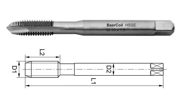
Technical drawing

| D1 |
4,94 mm |
|---|---|
| D2 |
6,0 mm |
| L1 |
70 mm |
| L2 |
14 mm |
| Diameter |
4 |
| Square |
4,9 mm |
Application – Sample materials
| Construction steels, case-hardening steels | Cutting speed vc in m/min | |
|---|---|---|
| 1.0050 | St 50-2 | 40 - 45 |
| 1.0718 | 11SMnPb30 | 40 - 45 |
| 1.7131 | 16MnCr5 | 40 - 45 |
| 1.7320 | 20MoCr3 | 35 - 45 |
| Alloyed steels, quenched and tempered steels | Cutting speed vc in m/min | |
|---|---|---|
| 1.0511 | C40 | 35 - 40 |
| 1.1269 | Ck85 | 35 - 40 |
| 1.1193 | Cf45 | 35 - 40 |
| 1.0601 | C60 | 35 - 40 |
| Stainless steels (ferritic, austenitic, martensitic) | Cutting speed vc in m/min | |
|---|---|---|
| 1.4105 | X6CrMoS17 | 15 - 20 |
| 1.4301 | X5CrNi18-10 (V2A) | 15 - 20 |
| 1.4571 | X6CrNiMoTi17-12-2 (V4A) | 15 - 20 |
| 1.4125 | X105CrMo17 | 15 - 20 |
| Pure aluminum, aluminum cast and wrought alloys Si < 10% (medium chip length) | Cutting speed vc in m/min | |
|---|---|---|
| 3.0205 | Al99 | 40 - 45 |
| 3.3315 | AlMg5 | 40 - 45 |
| 3.1645 | AlCuMgPb | 40 - 45 |
| 3.2373 | G-AlSi9Mg | 35 - 40 |
| Copper alloys, brass (long-chipping) | Cutting speed vc in m/min | |
|---|---|---|
| 2.0060 | E-Cu 57 | 40 - 45 |
| 2.0321 | CuZn37 (Ms58) | 40 - 45 |
| 2.1020 | CuSn6 | 40 - 45 |
Cutting speed vc [m/min] = (Outer diameter * π * speed) / 1000
Rotation speed n [1/min] = (Cutting speed in m/min * 1000) / (Outer diameter * π)
Feedrate programming [mm/min] = speed * pitch
Please note that the above cutting speeds are indicative and must be adjusted depending on lubrication and actuation.
Video instructions
Login

